
How to ensure communication with a PLC? Driver configuration | HMI programming course. Part 11.
During the course you will learn, among others:
- what communication protocols are available in Astraada HMI panels,
- how to configure panel communication with other devices,
- how to communicate between the HMI panel and the PLC using the Modbus TCP protocol.
In the previous episode "How to add a process file logging function? Saving data. | HMI panel programming course episode 10" you have added the ability to monitor historical data to your application and display it on a chart or table.
An important function of operator panels is the ability to display and process data from the PLC controller . To make this functionality possible, it is necessary to ensure communication between the operator panel and the PLC controller. In this part of the course, you will learn the communication protocols supported by Astraada HMI panels , you will learn how to configure the connection and how to exchange data between these devices.
HMI panel programming - course for automation engineers
- 1. How to create your first HMI panel project?
- 2. How to configure application settings? Interface and basic functions of the development environment.
- 3. How to add and edit operator screens?
- 4. How to design a graphical interface? Basic graphic objects used in HMI systems.
- 5. What types of variables are used in operator panels?
- 6. What are macros and how to use them in an HMI application?
- 7. How to configure alarms in operator panels?
- 8. How to create and modify recipes?
- 9. How to introduce application automation?
- 10. How to add the process file logging function? How to save data?
- 11. How to ensure communication with the PLC controller? Driver configuration.
- 12. How to limit access to the application? Operator passwords.
- 13. What additional functionalities may be useful when designing an applications?
In the project tree ( Project Manager ) on the left, find the Data Logger item and after selecting the option, right-click and select Add Data Logger . You can enter level as the name as below. Assign the monitored variable a level ( tag select button ) and set the Number of Samples value to 100 , which will affect the sampling rate when saving data.
Each application can use up to four different communication protocols (links). Some of them can be configured as SUBLINK, which makes it possible to query more devices within one protocol.
Some of the protocols available for these panels were created for specific automation solutions and devices (e.g. Emerson or SIMATIC S7). You can also create your own drivers in the Astraada HMI CFG software. To do this, depending on whether the connection is to be made via the COM port or the Ethernet port, select the option:
- Direct Link (COM) -> PanelMaster -> General Device (TCP/IP Slave)
or
- Direct Link (Ethernet) -> PanelMaster -> General Device (COM)
The Astraada HMI panel can work both as a Master device (initiating the connection) and as a Slave device (polling device).
E.g.: Astraada HMI – > Modbus Device/Slave (RTU) says that Astraada HMI will communicate as a Master in the Modbus RTU protocol. In this configuration, the panel will connect to Slave devices (Device/Slave (RTU)), as a device initiating all communication.
Modbus TCP protocol included
Open a recently saved project. In this step you will add the Modbus TCP protocol for the panel's communication with other devices.
Start by adding a new protocol by selecting Links in the design tree, then Add Link.
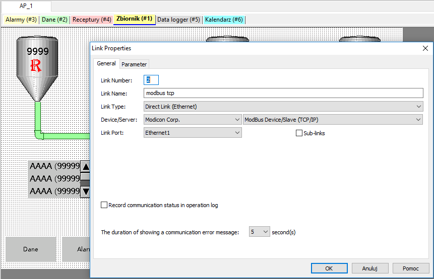
Set the window as above. Enter the name of the link modbus tcp. Select Direct Link (Ethernet) as the connection type. The device will act as a Slave, so select ModBus Device/Slave (TCP/IP) in the Device/Server field. In the Link Port field, select Ethernet1. In the next step go to the Parameter tab.
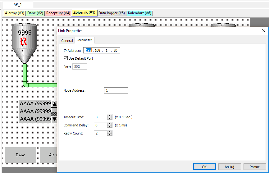
If you haven't checked the Sub-links option on the General tab, you can overwrite the IP address that will be used for this connection protocol. Port 501, which will be used for the connection, is the default setting for the Modbus TCP/IP protocol.
Set the values for the time to be measured while waiting for a response from the device (Timeout Time) and specify the number of times to retry to establish a correct connection with the device (Retry Count).
Now go back to the General tab and click the Sub-links option to add the ability to connect to multiple devices using a single protocol.
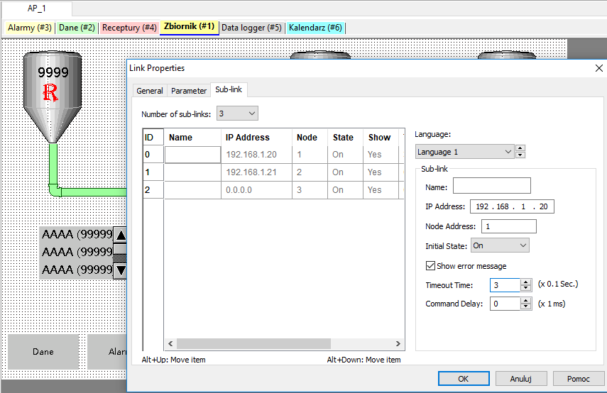
Configure the IP addresses of the devices used in this protocol correctly and reset the Timeout Time value for the correct connection to the device. Check the Show error message box to receive a connection error message. When the configuration is complete, confirm the changes by selecting OK.
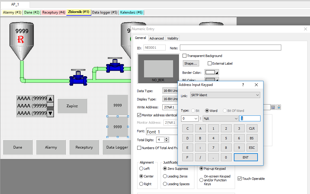
Return to the main application screen. Select the Numeric Entry object from the top Object menu, place it roughly in the centre of the screen and double-click on it to enter its configuration.
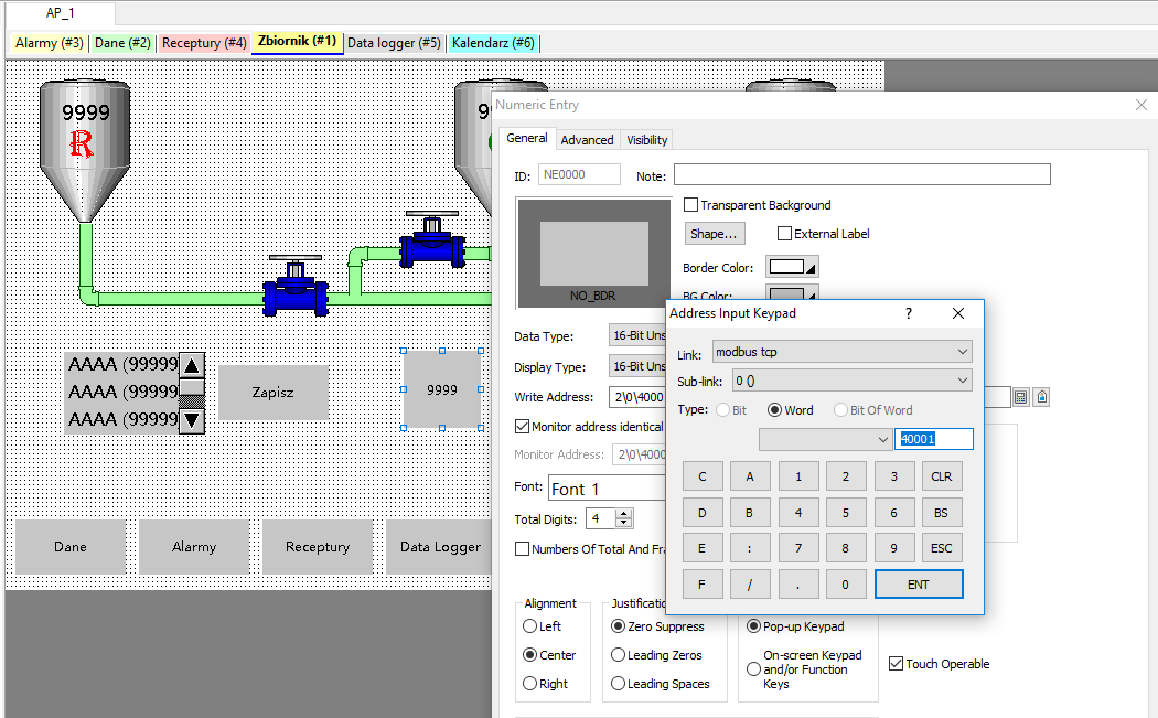
Select the Address Input Keypad button to the right of the Write Address item and select the following options:
- Link: modbus tcp (name of the protocol you created)
- Sub-link: 0()
- Address: 40001
Now add another communication protocol called SRTP client.
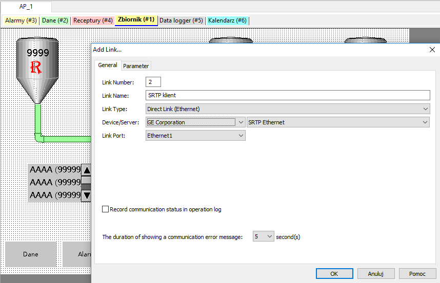
Select the options as shown above and go to the Parameter tab to set the connection properties. These will be the same as in the protocol added earlier.
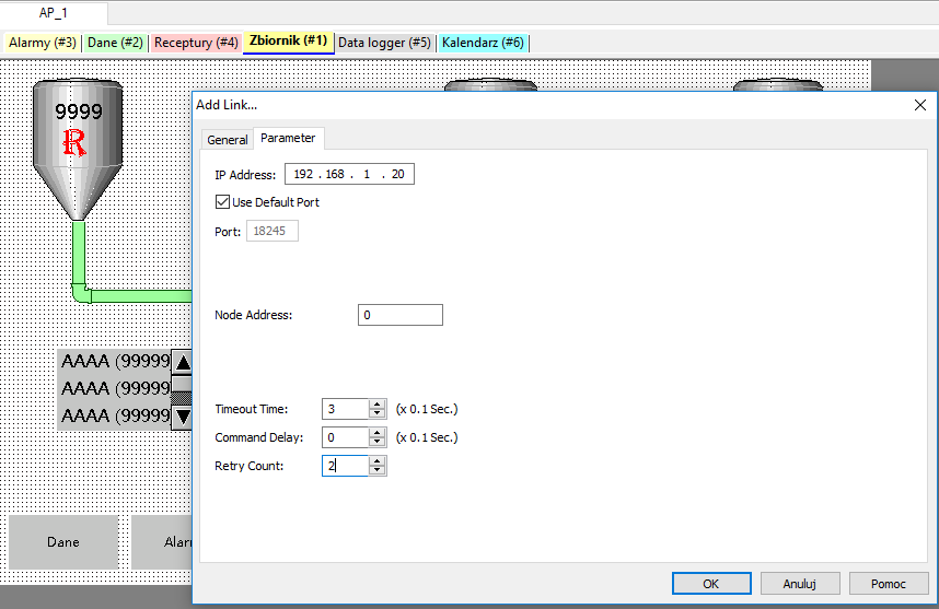
After configuring this protocol, add the Numeric Entry object again, place it under the previously added object and configure it in the same way as shown below.
Now add another protocol that allows you to assign a protocol address to the floating address in the software.
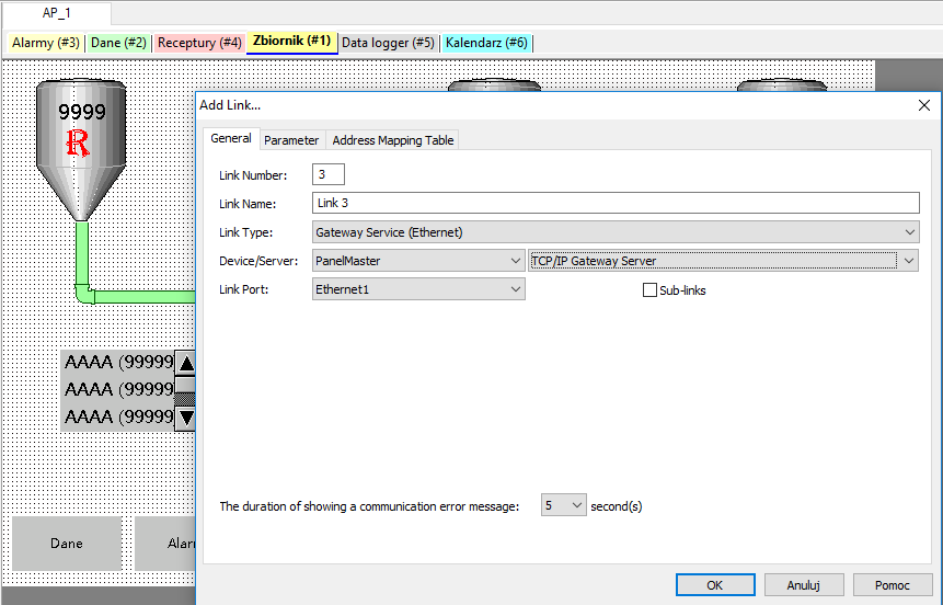
Configure the protocol as above. This connection allows communication between the panel and a PC via Ethernet connection and Modbus TCP/IP protocol.
Go to the Address Mapping Table tab, where you will assign protocol addresses to the internal application addresses.
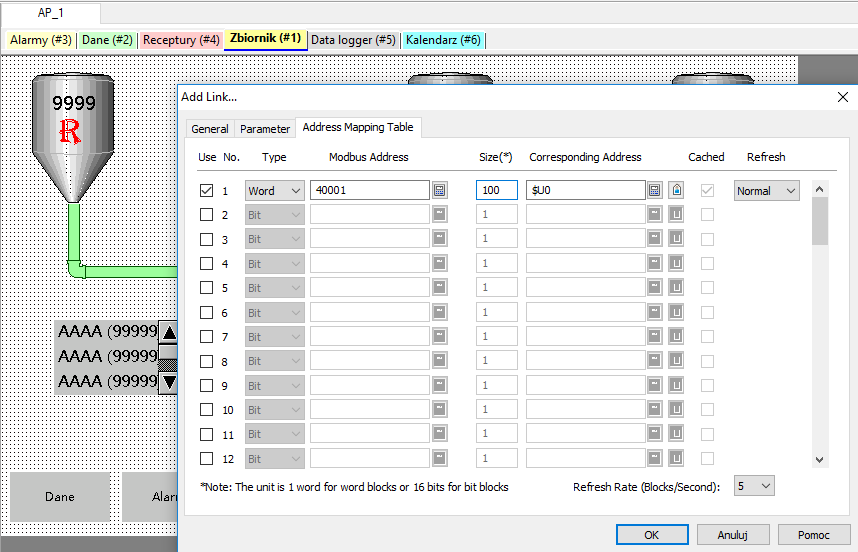
To do this, click the first box in the left column of Use to set up the connection. Configure in turn:
- Variable type Type: Word
- Modbus Address: 40001
- Size Map Size: 100
- Corresponding Address: $U0
In the next part of the course How to limit access to the application? Operator passwords. | HMI console programming course. Part 12 you will learn:
- the purpose of using passwords in the operator panel software,
- how to add and configure passwords,
- how to assign passwords to users,
- how to protect application functions and items with passwords.
Author:
Ewelina Szędzioł
