
How to add and edit operator screens? | HMI programming course. Part 3.
During the course you will learn, among others:
- How to add and configure a new screen
- How to design navigation between screens
- How to open windows using buttons and macros
In the previous article "How to configure application settings? Interface and basic functions of the development environment | HMI panel programming course episode 2" , you learned how to adjust the main application settings on the operator panel and learned the basic objects that can be used in building applications. In this part of the course, you will learn how to add and configure application screens.
HMI panel programming - course for automation engineers
- 1. How to create your first HMI panel project?
- 2. How to configure application settings? Interface and basic functions of the development environment.
- 3. How to add and edit operator screens?
- 4. How to design a graphical interface? Basic graphic objects used in HMI systems.
- 5. What types of variables are used in operator panels?
- 6. What are macros and how to use them in an HMI application?
- 7. How to configure alarms in operator panels?
- 8. How to create and modify recipes?
- 9. How to introduce application automation?
- 10. How to add the process file logging function? How to save data?
- 11. How to ensure communication with the PLC controller? Driver configuration.
- 12. How to limit access to the application? Operator passwords.
- 13. What additional functionalities may be useful when designing an applications?
How to add and configure a new screen?
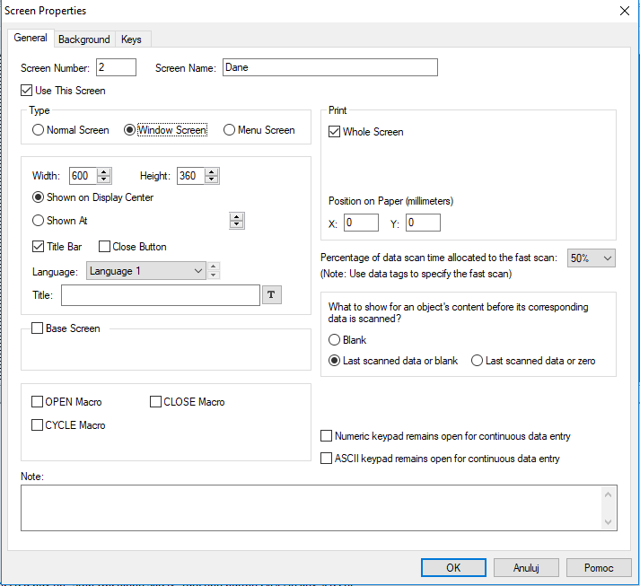
Open the screen settings window, which can be found in the design tree, in the Screen > Screen 1 > Properties tab. In the Type section, specify whether the screen is to be displayed only when you call it up - e.g. by pressing a button (Window Screen), or whether it is to be a standard screen, displayed in the entire window (Normal Screen). If the screen is of the Windows Screen type, you can specify its dimensions.
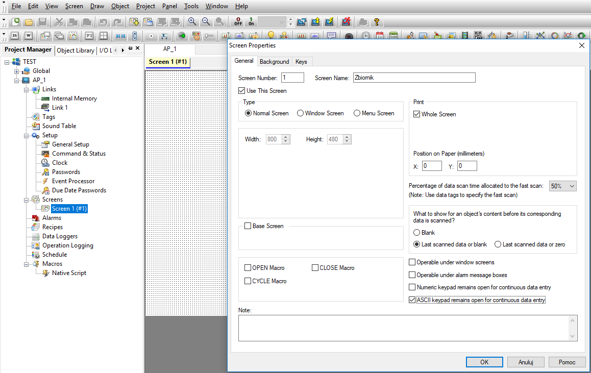
You can check the (Base Screen) option if you want the screen to be treated as the main screen of the application. You can also assign macros to the screen, which can be called when opening (OPEN Macro), closing (CLOSE Macro), or when displaying a given screen on the panel (CYCLE Macro).
The Print section will allow you to configure screen printing parameters if you use a printer.
In the next section, specify what should appear on the screen at startup if the application contains numeric data. For fast-changing processes, it is worth selecting the quick scan option (refreshing variable values). If you want to have full access to the screen also when displaying alarms (Operable under alarm message boxes) or other windows (Operable under windows screens), select the appropriate options.
Rename the screen to TANK by editing the Screen Name field.
How to plan navigation between screens?
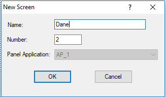
In the next step, add a new screen called Data by selecting the Screen > New Screen tab from the top menu of the program. In its settings, check the Window Screen option to display it only when invoked from the base screen.
Then double-click on the first object to open the configuration window. In the Monitor Address window, enter the value as shown below.
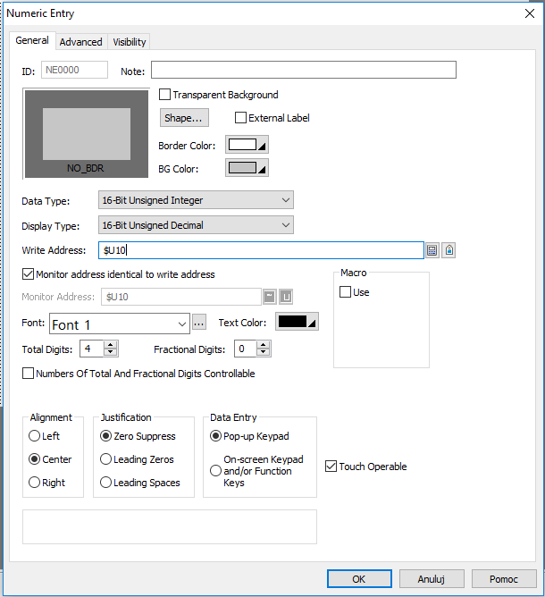
Also assign the address $U11 to another object.
How do I start the software and start the simulation?
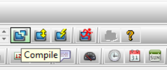
Now create a program and run the simulation. To create a program, click on Compile in the top menu of the program.
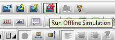
Once the program is properly compiled, proceed to the simulation by selecting Run Offline Simulation from the same menu.
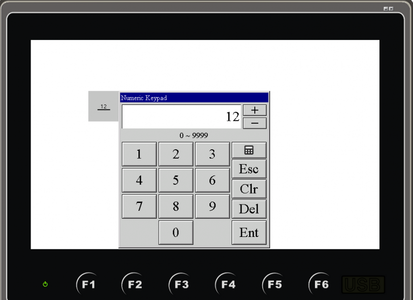
A screen with two objects is displayed. Double-click on an object and you will see the system keyboard allowing you to enter a numeric value.
Good to know
At this stage, you can explore the Astraada HMI CFG off-line simulation environment by changing the values of individual objects.
After closing the simulator window, you will see the simulation configuration window.
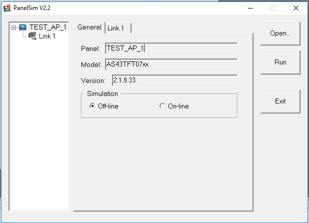
What is important in this case is the ability to change the type of simulation from Off-line to On-line. In the case of online simulation, the panel transmits data via ports defined in the project. This allows you to connect the panel to a computer with an external device simulator, e.g. for testing/service purposes. Once you are familiar with the simulator, close the window with the Exit button.
Then, from the same menu, select the Download option to display the window for uploading information to the HMI panel.
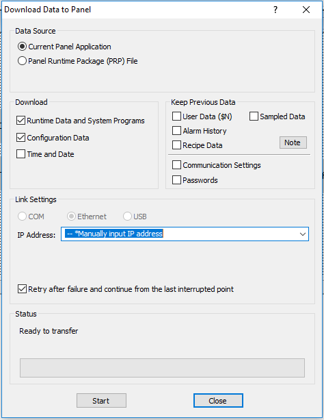
In this window you can choose what data you want to upload to the panel together with the application. In the Keep Previous Data tab, you can also declare which data is not to be changed when uploading the application to the panel - so that it is not overwritten after launch.
From this level you can also select the port that will be used to connect to the panel (COM, Ethernet, USB). If you do not intend to change the configuration of uploading applications to the HMI panel in the future, you can select the Download Immediately option from the same menu.
How to plan navigation between screens?
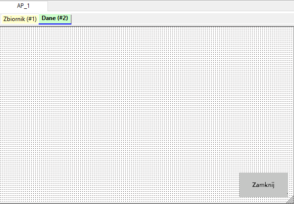
In the next step, add a new screen called Dane by selecting Screen > New Screen from the top menu of the application. In your settings, select Window Screen to show it only when called from the main screen.
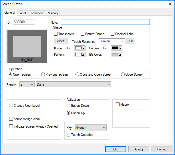
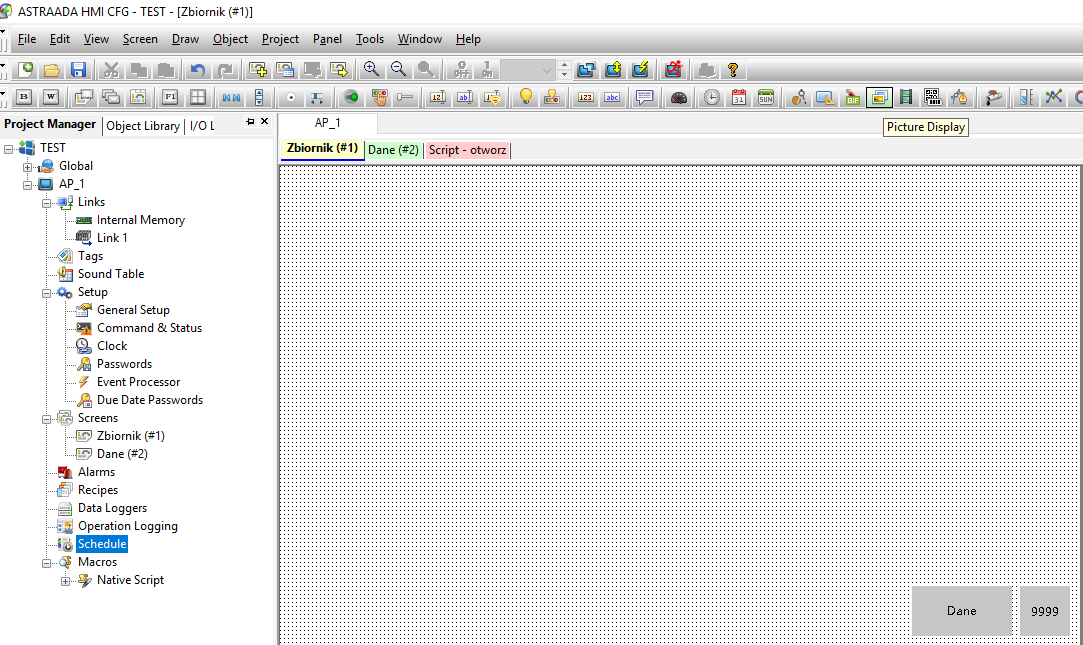
Confirm the settings with OK and go to the first screen. Re-navigate it by selecting the Screen Properties tab and edit the Screen Name field to Zbiornik. Then select the Object > Screen Button tab in the top menu and place the button in the bottom right corner of the screen as shown below.
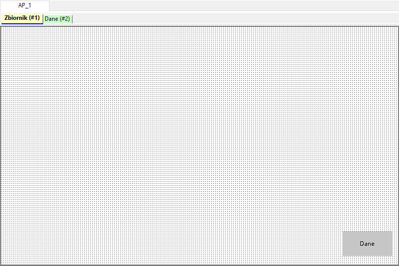
To change the label of a button, in the Label tab, change the name from Screen to Dane, and in the Screen field, select the screen Dane. This button will display the Dane screen.
Note: Be sure to periodically record the current development progress by clicking on the floppy disk button in the top left corner of the programme.
Now go to the Data screen and place the Screen Button in the bottom right corner of the screen. Assign it the Close Screen action, and change the label on the Label tab.
To check that you have included all objects correctly, you can run the simulation in the simulator described above.
If something doesn't work as it should, go back to the previous steps and check that you haven't made a mistake. If everything is OK, the Dane button should show the pop-up screen, and the Close button should return to the Zbiornik screen only.
Then go to Command & Status in the design tree on the left.
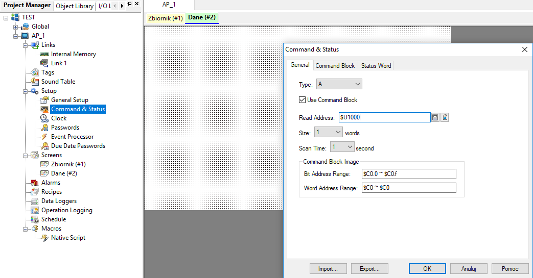
Configure the General tab as shown above and go to the Status Word tab.
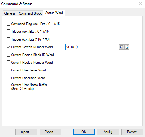
Select Current Screen Number Word and enter $U1010. This will allow you to monitor the data used by the application and display it on the screen.
Important: If you don't understand a function or want to know more about a specific option, click the Help button.
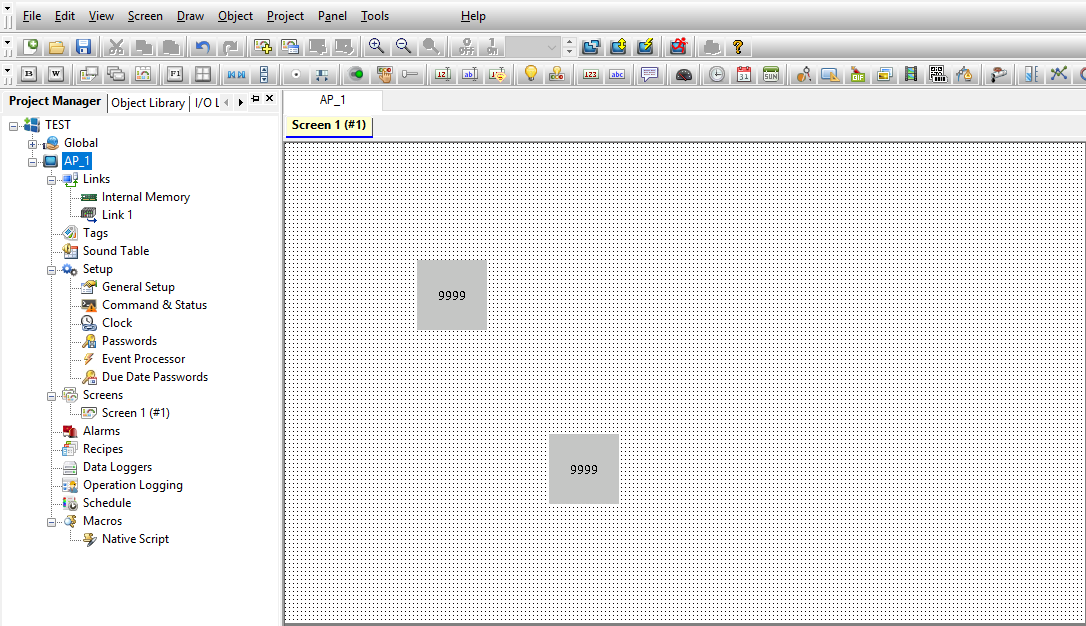
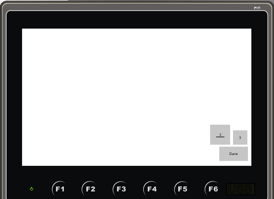
Now add the Numeric Entry and Numeric Display objects and position them so that the display looks like the one shown below.
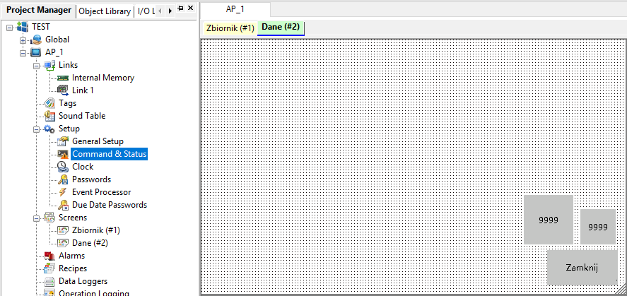
Assign the variable $U1000 to both objects by entering it in the respective Write Address and Monitor Address windows to overwrite and monitor the value of this variable.
After checking the application's behaviour in the simulator, remove the unnecessary objects so that only the Dane button and the Numeric Display object remain - as shown below. This will expand the display in the next section of the course.
Important: If you don't understand a feature or want to learn more about a specific option, click the Help button.
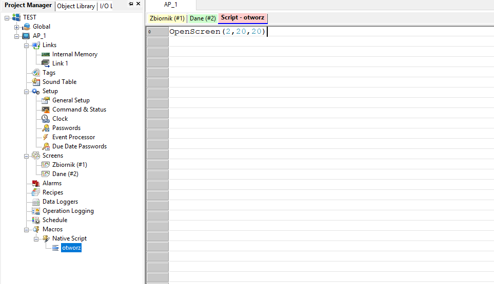
Now create your first Macro file. Expand the Macros tab and right-click on Native Scripts and select Add Script. In the Macro Name field, enter OPEN, then create the macro shown below:
Now add the Bit Button to your home screen and open its settings.
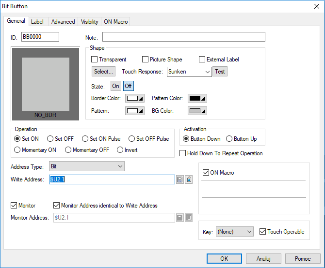
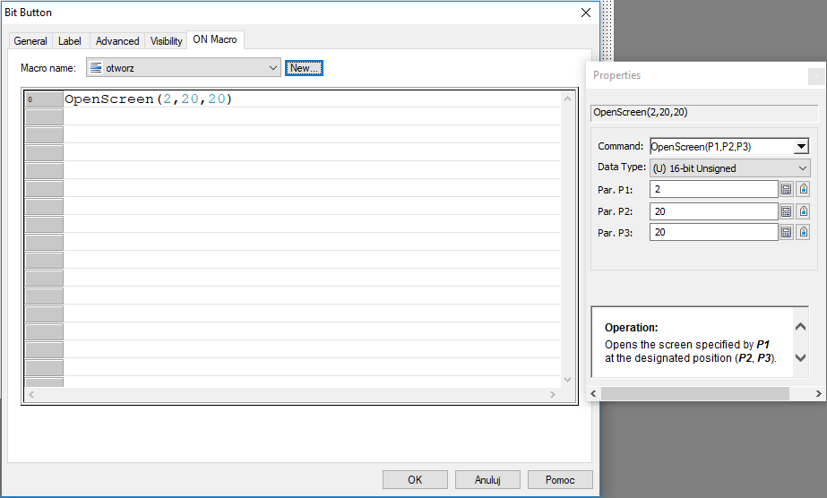
Assign it an appropriate bit and mark the ON Macro option, thanks to which you will be able to assign a macro that will be executed when the button is pressed. In the ON Macro tab, select the created OPEN script.
Save, compile and test the program. When clicked, the button marked OFF should behave similarly to the Screen Button and open the DATA window.
Important: To better understand the functions written in macros, review the Properties window that appears when you write a macro when entering a function.
In this window you will find information about the tasks of individual functions and tips on how to correctly assign arguments to them (if you have ever used any of the popular programming languages, creating even advanced macros should not be difficult for you).
Note: Remember to compile the program before each simulation using the Compile button if any changes have occurred in the program.
After checking the operation of the program in the simulator, remove unnecessary objects so that only the Data button remains. You will expand the screen prepared in this way in the next section of the course.
In the next part of the course "How to design a graphical interface? Basic graphic objects used in HMI systems. | HMI panel programming course episode 4" you will learn:
- what graphic objects are worth knowing at the beginning (tank, mixer, valve, bar chart, signal lamp, pipeline),
- how to adjust the size and appearance of graphic objects.
Authors:
Paweł Podsiadło
Ewelina Niziołek
